
Uses, Advantages & Benefits
The streamlined thrust drive system reduces the number of components, minimizing potential failure points. By positioning the engines outside the fuselage, cabin noise and vibration are significantly reduced, while safety is improved by distancing the highest potential ignition source in case of an accident. Additionally, increased rotor inertia enhances safety by helping to prevent a rapid loss of rotor RPM in the event of engine failure.
The thrust drive system's high rotational energy gives the pilot more time to react in the event of a complete power loss before autorotation. Traditional helicopters, experience parasitic drivetrain power losses during autorotation hindering safe autorotation and limiting autorotation performance.
Eliminating the tail rotor
-
Elimination of constant opposing force requirements and mechanisms
-
Yaw control using a simple integrated mechanism
-
Tail boom is optional
-
Tail rotor and boom strike eliminated
-
Tail rotor failure is not an issue
-
Tail can be eliminated with electric yaw control
-
Elimination of conventional drive components reduces noise and vibration
-
Eliminate the cost and weight of components
-
Engine power is directly used to generate lift, not to gear reduction systems and counter torque components
-
Increased payload for available shaft power or the same payload with a lower shaft power requirement
-
Reduced cost and complexity of manufacturer and maintenance

In this configuration of the thrust drive system, the engines provide direct thrust through a separate, isolated structure. As with most thrust drive system designs, when four or more engines are used, two or more can be shut down during forward flight to improve fuel efficiency when the aircraft is not operating at full load.

This configuration features the thrust tubes fully integrated into the rotor blades.

The basic compound configuration utilizes microturbine engines to provide reaction power for takeoff, landing, and helicopter maneuvering. Once the aircraft reaches sufficient forward speed, the microturbines are turned off, and engines with propellers mounted on stub wings take over to provide forward thrust, improving fuel economy. Meanwhile, the rotor blades and thrust tubes continue to rotate, providing partial lift in a gyrodyne configuration. This system can also be configured to use only the thrust tubes for lift, functioning as rotor blades.
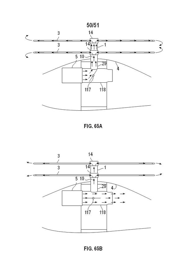
An alternative configuration features an indexing clutch that stops the thrust tubes perpendicular to the fuselage. In this setup, a servo rotates one thrust tube 180 degrees, aligning the airfoils to both point forward, providing lift alongside the engines for forward propulsion. The turbine engines in this configuration are fully compatible with hydrogen fuel, and either electric or turbine engines can be used interchangeably for zero-emission rotor power or forward propulsion.
A historical example of a gyrodyne is the Faraday Rotodyne, which performed exceptionally well, reaching speeds of 200 mph in the 1950s while carrying up to 40 passengers. Despite its success, it was hindered by the extremely loud, air-fed rockets at the rotor tips, which produced up to 120 dB of sound, even at 600 feet away, preventing it from entering full production.
The Thrust Drive System avoids this issue, producing sound emissions similar to or lower than a conventional helicopter due to the enclosed engines within a sound-abating fairing acting similarly to a muffler and thrust tubing. The long tubes that channel the engine thrust act similarly to a car’s exhaust pipe, further reducing noise. As a result, the gyrodyne configuration with the Thrust Drive System is not only achievable but practical for use in urban environments, utilizing existing helipads and city centers due to its reduced noise emissions.
The described configuration is designed to create a fast compound helicopter with fewer moving parts, reducing potential failure points and simplifying maintenance. During takeoff, a valve directs most of the engine's "warm cycle" pressure through the rotor shaft, distributing it to short, counter-rotating airfoil-shaped thrust tubes (which serve as rotor blades) to generate lift for takeoff and hover.
As the aircraft transitions to high-speed forward flight, the valve adjusts to direct the majority of engine pressure toward forward propulsion while reducing pressure to the counter-rotating thrust tubes, as the need for induced power decreases. Fly-by-wire servo flaps integrated into the rotor blades manage flight control, eliminating the need for complex, maintenance-intensive rotor head control systems.
Like other Thrust Drive System designs, this configuration avoids heavy transmissions and conventional drive components. Additionally, compressor bleed air is employed for yaw control and auxiliary reaction controls, streamlining the system even further.
Additional Safety and Serviceability Enhancements
-
In certain configurations engines no longer directly embedded above or next to fuel tanks improving safety in case of a crash
-
Flexible aircraft shape and footprint
-
Operate from same landing pads and facilities as conventional helicopters
-
Existing pilot skills and training are fully compatible
-
Major aircraft components are the same or similar in construction
-
Reduction or elimination of unloaded rotor mast bumping by incorporating gyroscopic damping of power system onto the rotor head and side thrust produced by the tail rotor
-
Improved safety has the potential to lower insurance cost

The following drawings depict different thrust drive configurations, which can be customized to meet specific performance requirements depending on the application.
