
Frequently Asked Questions
Frequently Asked Questions
How does the Thrust Drive System work?
Engines channel thrust through tubes, which is then expelled from nozzles to generate the torque required to power the rotor blades. This system removes the need for transmissions, gearboxes, driveshafts, long tail booms, and counter-torque devices.
Why is a tail rotor not required with the Thrust Drive System?
In a conventional helicopter, the engine is attached to a gearbox that converts engine power into mechanical torque to rotate the rotor shaft. When force is applied to spin the shaft an equal and opposite amount of force is created that "pushes" back against the gearbox and in turn wants to spin the helicopter in the opposite direction. To prevent the helicopter from spinning out of control an anti-torque device such as a tail rotor uses some of the engine power to counteract the force created from driving the rotor shaft. In the thrust drive system engine thrust is converted to the torque that is delivered directly to the rotor shaft which is isolated from the fuselage eliminating the need for a tail rotor. The resulting equal and opposite force of the thrust coming from the thrust tubes are what provides the "push" to spin the thrust tubes and connected rotor shaft in the opposite direction to thrust exiting the tubes. Without the need to continuously mitigate torque from the engines, only a small force applied directly to the fuselage is required to provide yaw control. The pilots' pedal input operates a fixed vertical stabilizer, a set of energized electromagnetic coils act against the outer edge of a magnetic disk attached to the rotor shaft to provide yaw control of the aircraft. Another simple option for yaw control is an electric brushless fan unit located behind the fuselage with an adjustable pitch, the fan to be only activated during takeoff and landing. Ideally, the fuselage profile should be as streamlined as possible not only for good aerodynamic performance but also to limit the surface area that wind can act against causing uncommanded movement.
How is the Trust Drive System safer than a conventional helicopter?
The streamlined Thrust Drive System significantly reduces the number of drive system components and minimizes potential failure points. With no gearbox, tail rotor, or associated drivetrain, maintenance is greatly simplified. The engines can be positioned far enough from the fuselage to not only dramatically lower cabin noise and vibration but also reduce the risk posed by the largest potential ignition source in case of an accident. The absence of a gearbox and drivetrain also frees up additional fuselage space.
This system enhances safety by lowering the risk of vortex ring state and increasing rotor inertia, which helps prevent a rapid loss of rotor RPM during emergencies or power loss, greatly improving autorotation capability. Additionally, the elimination of a tail rotor removes the danger of tail rotor-related accidents altogether.
Does this new technology allow improved load capacity compared to a conventional helicopter?
The removal of the gearbox, tail rotor, tail boom, and associated drivetrain weight allows for an increased useful payload capacity compared to a traditional helicopter.
How does a reaction-driven helicopter reduce the vortex ring state?
The thrust expelled from the blade tips in a tip-jet helicopter helps reduce the likelihood of vortex ring state. This is because the thrust at the tips creates a more stable airflow and reduces the chances of the helicopter's descent rate causing the disturbed airflow that leads to the votex ring state.
How does the Thrust Drive System compare to past tip jet or pressure jet technologies?
Previous attempts to implement reaction drive systems in helicopters have typically relied on either separate engine-powered compressors to generate thrust or engines directly attached to the rotor blade tips. In pressure jet configurations, a large centrifugal compressor located in the fuselage supplied pressurized air to the rotor blades to produce the necessary reaction power. However, the engine or auxiliary power unit (APU) required to maintain sufficient pressure through the rotor blades was significantly larger and less fuel-efficient compared to conventional turboshaft engines. The additional weight and higher fuel consumption posed disadvantages against traditional helicopter technologies. Furthermore, delivering thrust through narrow diameter tubes embedded in the thin rotor blade profiles at high pressures resulted in low overall system efficiency.
Tip jet helicopters, which had engines positioned at the rotor blade tips, offer another example of a reaction drive system. One of the most notable examples is the Hiller Hornet. The Hornet, like similar designs, used ramjet engines attached directly to the rotor blade tips, generating an impressive 31 pounds of thrust per engine. Despite this, the ramjets suffered from extremely high fuel consumption, severely limiting the aircraft's operational range. Moreover, the lack of safe autorotation capability in the event of power failure, due to the high drag generated by the tip-mounted engines moving at maximum velocity, added a significant safety risk. These issues, along with other inefficiencies, ultimately led to the discontinuation of these designs. More details can be found at Fantasy of Flight.
The Thrust Drive System distinguishes itself from these earlier efforts through a vastly improved thrust delivery mechanism, which decouples power from the rotor blades via a clutch system, greatly enhancing safety during power loss. Unlike previous pressure jet designs that were inefficient due to high-pressure, low-volume airflow, the Thrust Drive System operates on high-volume, low-pressure propulsion, contributing to quieter operation. Additionally, the system's higher rotor inertia allows for more time to react in the event of power failure. The use of modern, compact, and affordable engine technologies further simplifies manufacturing and maintenance, making the Thrust Drive System a far more viable and efficient solution than its predecessors.
Can the Thrust Drive helicopter operate with zero-emissions?
The Thrust Drive System is capable of operating on both electric and fuel-based power. For zero-emissions operation, hydrogen fuel presents an efficient option, as it can either generate electricity for the electric motors with only water vapor as a byproduct, or be burned directly in the engines to produce ultra-low emissions. One key advantage of hydrogen is its energy density. The diesel fuel used in our test engine has an energy density of 45.5 megajoules per kilogram (MJ/kg), which is slightly less than gasoline’s 45.8 MJ/kg. In comparison, hydrogen boasts an energy density of around 120 MJ/kg—nearly three times that of diesel or gasoline.
In electrical terms, hydrogen’s energy density is equivalent to 33.6 kWh of usable energy per kilogram, compared to diesel's 12–14 kWh per kilogram. This means that 1 kg of hydrogen, when used in a fuel cell to power an electric motor, provides about the same energy as a gallon of diesel. Additionally, hydrogen fuel cells have a significantly higher energy-to-weight ratio, up to ten times greater than lithium-ion batteries, offering greater range, reduced weight, and smaller volume requirements.
Regarding safety, it’s worth noting that diesel and jet fuel have an autoignition temperature of only 300 degrees Fahrenheit, while hydrogen’s autoignition temperature exceeds 1,000 degrees Fahrenheit, further emphasizing its safety advantages in certain applications.
How do you get rid of the long tail boom?
Since an anti-torque system is no longer necessary, yaw control can be achieved using an electric solid-state actuator integrated into the rotor system, optionally paired with a simple vertical stabilizer and rudder. Alternatively, a horizontal stabilizer with dual rudders can replace a single rudder behind the fuselage. Yaw control can also be maintained without a rudder or tail boom by utilizing a magnetic rotor affixed to the rotor shaft. Energizing copper coils attached to the fuselage enables active control through adjustments in electrical polarity and controlled current output. This setup operates similarly to a brushless electric motor, with the rotor shaft functioning as the motor's axle and the fuselage acting as the motor’s housing.
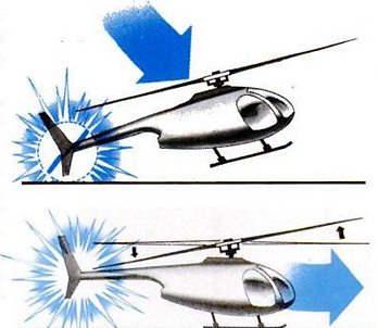
▲Most accidents involving conventional helicopters take place on landing. At top, the pilot flares the craft and the tail boom strikes the ground. Above, chopper balloons forward to level off and the main rotor tilts back, cutting into the tail.
Can cost of producing and owning a helicopter be reduced by the Thrust Drive System?
The removal of the gearbox, tail rotor, and related drivetrain components significantly simplifies helicopter manufacturing and reduces both production and ownership costs. Engine maintenance and replacement are also much easier. Additionally, once the technology has demonstrated a reliable track record, it is expected that insurance costs will be lower.
How is autorotation improved?
The high rotational kinetic energy of the thrust drive system provides the pilot with more time to react in the event of a complete power loss before autorotation begins. Additionally, the system avoids power loss from failed drive components during autorotation. In contrast, conventional helicopters experience transmission friction even when engine power is lost, often requiring negative anti-torque thrust to counteract friction during autorotation. Further, if any critical drive component in a traditional helicopter fails, it can introduce additional friction that hinders safe autorotation.
What aircraft size does this technology apply to?
This propulsion technology can be utilized by helicopters of all sizes, from small drones to heavy-lift operations. The Thrust Drive System is scalable and adaptable, offering a significantly simplified and more efficient helicopter design. This leads to enhanced serviceability and safety due to the reduced number of components, as well as lower costs associated with the power system. Envision a scenario where a spare engine can be carried onboard and easily replaced by simply removing a set of fasteners, an electrical coupler, and a fuel connector. The objective is not only to improve helicopter safety, reliability, and cost of ownership but also to make the Thrust Drive System easy to inspect and maintain, while minimizing the components that have historically contributed to critical failures in conventional drivetrain systems.
Can the Thrust Drive System reduce noise?
With the absence of a tail rotor, tail rotor noise is entirely eliminated. The engines are enclosed within sound-dampening aerodynamic fairings, significantly reducing high-frequency noise, while the thrust tubes further mitigate low-frequency noise from the engine exhaust.
How are the flight characteristics compared to a conventional helicopter?
All controls in the Thrust Drive System function similarly to those of a typical helicopter, providing comparable responsiveness. The system adds a greater gyroscopic effect, enhancing stability and creating a more "locked-in" feel, offering increased resistance to uncontrolled movements when encountering wind gusts or turbulence. This stability allows the aircraft to maintain its heading and controlled position more effectively during maneuvers, as demonstrated in historical videos of reaction drive helicopters hovering stably, even with the pilot’s hands off the controls. Control responsiveness remains intact, with less need for damping or flybar stabilization.
A notable flight characteristic of the thrust drive helicopter is that it hovers completely flat and level, unlike conventional tail-rotor helicopters that typically hover with a slight left-side tilt due to the need to counteract tail rotor thrust with main rotor tilt. Larger rotor blades with lower disk loading have been tested with the prototype, which has significantly increased takeoff weight capacity without inducing any adverse yaw effects during fast blade pitch transitions. These improvements are made possible by the absence of counter-torque requirements, with only a slight increase in rotor RPM recovery during abrupt positive pitch changes.
Additionally, the system allows for offloading of the main rotor blades during hover and low-speed operations by introducing a small amount of positive pitch into the thrust tube airfoils, which reduces main rotor noise and enhances safety when operating with higher takeoff weights. Co-rotating thrust tube airfoils and rotor blade structures can be slightly offset to reduce wake-induced noise levels, based on recent research findings.
Moreover, the isolation of rotor shaft and system vibrations from the fuselage is easier, as there are no powertrain connections transmitting vibrations throughout the fuselage. The rotor shaft angle can also be adjusted mid-flight to optimize efficiency without interference from powertrain components.
How efficient is the thrust delivery with a turbojet engine?
The turbojet engine generates thrust at high temperature and velocity, which is not optimal for efficient flow through thrust tubing. To mitigate this, a thrust augmenter is positioned immediately behind the engine with a small air gap, allowing cooler ambient air to mix with the exhaust. This process increases mass flow while reducing exhaust temperature, effectively transforming the engine’s high-velocity, low-pressure thrust into a lower-velocity, higher-pressure flow for more efficient delivery through the thrust tubing. By minimizing internal turbulence and friction losses, this method significantly enhances overall efficiency compared to previous thrust delivery approaches in tip jet helicopters. Additionally, the thrust tubing length from the augmenter to the output nozzle is kept as short as possible to maximize system efficiency while reducing structural stresses and minimizing the weight of power system components.
©2025 by ThrustDrive.com